Å koble til en LCD på Arduino er forholdsvis enkelt. Man trenger kun LCD, brødbrett, testledninger, 

Kretsen
Det første man bør gjøre er å lodde fast ei pinnerekke under LCD-kretskortet, for å få best mulig kontakt når displayet er tilkoblet:

Lar man være å gjøre dette, vil ikke skjermen virke. Det vil kun dukke opp firkantede svarte bokser, fordi noen pinner har for dårlig tilkobling.
Etterpå følger man så prosjektet «Liquid Crystal Displays (LCD) with Arduino» og får ca noe som ligner på følgende oppsett:
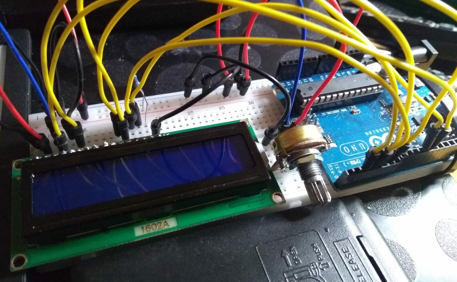
Alle disse koblingene kan virke komplekse og uoversiktlige, men det er de ikke. De gule ledningene er for data, de røde er for 5V og svart er minus/jord. Blå blir et slags unntak, da den er ingen av delene; den gir finjustert spenning inn på LCD for å regulere skjermkontrast. Høres kanskje innviklet ut, men det er det ikke.
Arduino-kode
For å vise tekst på displayet velges et av kodeeksemplene på prosjektnettsiden:
#include <LiquidCrystal.h>

const int rs = 12, en = 11, d4 = 5, d5 = 4, d6 = 3, d7 = 2;
LiquidCrystal lcd(rs, en, d4, d5, d6, d7);

void setup() {
   lcd.begin(16, 2);
   lcd.print("Hello, world!");
}

void loop() {
   lcd.setCursor(0, 1);
   lcd.print(millis() / 1000);
}
Denne kodesnutten og de andre virker greit. Displayet viser tekst. Case closed.
Embedded C
Den reelle utfordringen er å skrive en fungerende løsning i Embedded C, så man kan tweake og gjøre med koden som man vil …
Pinner
Først trengs en oversikt over hvilke porter og pinner som er brukt. Med info fra prosjektnettsiden over og kart for hvilke Arduino-pinner som er koblet til hvilke ATmega328P-pinner, får man følgende oversikt:
LCD-pinne        Arduino-pinne          ATmega328P-pinne
--------------------------------------------------------
LCD RS           digital pin 12         PB4
LCD Enable (E)   digital pin 11         PB3

LCD D4           digital pin 5 	        PD5
LCD D5           digital pin 4	        PD4
LCD D6           digital pin 3	        PD3
LCD D7           digital pin 2	        PD2
De andre pinnene forandres ikke, de kan stå der de står. Heller ikke potensiometeret trenger å kobles om.
Kode
Jeg var (u)heldig og fant noe gammel kode som ordner LCD i C. I hvertfall mer eller mindre. Dermed slipper jeg å skrive alt fra scratch. Noe som sannsynligvis ville tatt flere uker.
Men en ting jeg ikke likte i denne koden var at porter og pinner var hardkodet med #define. Derfor måtte man ha oppdatert disse opplysningene hver gang noe var feil.
Dette valgte jeg å gjøre om, så all informasjon om porter og pinner mates fra main() eller der LCD-en styres fra. Dette gjøres via en struct. Da blir alt på en plass, dette er ryddigere. Syns i hvertfall jeg.
main.cpp
#define F_CPU 16000000UL

#include <avr/io.h>
#include <util/delay.h>

#include "LCD.hpp"

int main(void)
{
   // ---------------
   // Setup:

   /*
      LCD pin         Arduino pin        ATmega328P pin
      -------------------------------------------------
      LCD RS          digital pin 12     PB4
      LCD Enable (E)  digital pin 11     PB3

      LCD D4          digital pin 5      PD5
      LCD D5          digital pin 4      PD4
      LCD D6          digital pin 3      PD3
      LCD D7          digital pin 2      PD2
   */

   struct PortsAndPinsSetupLCD setup;

   // Ports
   setup.RS_PORT = &PORTB;
   setup.E_PORT = &PORTB;
   setup.D7_PORT = &PORTD;
   setup.D6_PORT = &PORTD;
   setup.D5_PORT = &PORTD;
   setup.D4_PORT = &PORTD;

   // Pins
   setup.RS_PIN = PB4;
   setup.E_PIN = PB3;
   setup.D7_PIN = PD2;
   setup.D6_PIN = PD3;
   setup.D5_PIN = PD4;
   setup.D4_PIN = PD5;

   // Data direction
   DDRB |= (1<<setup.RS_PIN);
   DDRB |= (1<<setup.E_PIN);
   DDRD |= (1<<setup.D7_PIN);
   DDRD |= (1<<setup.D6_PIN);
   DDRD |= (1<<setup.D5_PIN);
   DDRD |= (1<<setup.D4_PIN);


   // ---------------
   // Text:

   uint8_t text1[] = "LCD-display for";
   uint8_t text2[] = "AVR, programmert";
   uint8_t text3[] = "i Embedded C og";
   uint8_t text4[] = "virker dritbra!!";


   // ---------------
   // Testing:

   // Write
   lcd_init_4p(setup);

   while (1) {

      lcd_clear(setup);
      lcd_goto_line(0, setup);
      lcd_write_string_4p(text1, setup);
      lcd_goto_line(1, setup);
      lcd_write_string_4p(text2, setup);
      _delay_ms(3000);

      lcd_clear(setup);
      lcd_goto_line(0, setup);
      lcd_write_string_4p(text3, setup);
      lcd_goto_line(1, setup);
      lcd_write_string_4p(text4, setup);
      _delay_ms(3000);
   }
}
LCD.hpp
#ifndef LCD_HPP_
#define LCD_HPP_

#include <avr/io.h>
#include <util/delay.h>

/*
   First author:  Donald Weiman
   Date:          September 16, 2013
   Summary:       4-bit data interface, busy flag not implemented.

   Second author: Ove Bakken
   Date:          March 20, 2023
   Summary:       Slightly modified implementation.
                  Every functions is fed the necessary ports and pins.
                  Does not rely upon hardcoded #defines that needs changing.
*/

// Config
struct PortsAndPinsSetupLCD {

   // Ports
   volatile uint8_t *RS_PORT;
   volatile uint8_t *E_PORT;
   volatile uint8_t *D7_PORT;
   volatile uint8_t *D6_PORT;
   volatile uint8_t *D5_PORT;
   volatile uint8_t *D4_PORT;

   // Pins
   volatile uint8_t RS_PIN;
   volatile uint8_t E_PIN;
   volatile uint8_t D7_PIN;
   volatile uint8_t D6_PIN;
   volatile uint8_t D5_PIN;
   volatile uint8_t D4_PIN;
};

// Screen locations
#define START_LOCATION_LINE_1     0x00           // start of line 1
#define START_LOCATION_LINE_2     0x40           // start of line 2

// Screen instructions
#define INSTRUCTION_SET_4BIT      0b00101000     // 4-bit data, 2-line display, 5 x 7 font
#define INSTRUCTION_ON            0b00001100     // display on, cursor off, don't blink character
#define INSTRUCTION_OFF           0b00001000     // turn display off
#define INSTRUCTION_RESET         0b00110000     // reset the LCD
#define INSTRUCTION_CLEAR         0b00000001     // replace all characters with ASCII 'space'
#define INSTRUCTION_ENTRY_MODE    0b00000110     // shift cursor from left to right on read/write
#define INSTRUCTION_SET_CURSOR    0b10000000     // set cursor position
#define INSTRUCTION_RESET_CURSOR  0b00000010     // return cursor to first position on first line

// Function prototypes
void lcd_init_4p(PortsAndPinsSetupLCD);
void lcd_write_4p(uint8_t, PortsAndPinsSetupLCD);
void lcd_write_instruction_4p(uint8_t, PortsAndPinsSetupLCD);
void lcd_write_character_4p(uint8_t, PortsAndPinsSetupLCD);
void lcd_write_string_4p(uint8_t *, PortsAndPinsSetupLCD);
void lcd_clear(PortsAndPinsSetupLCD);
void lcd_goto_line(int, PortsAndPinsSetupLCD);

#endif /* LCD_HPP_ */
LCD.cpp
#include "LCD.hpp"

void lcd_init_4p(PortsAndPinsSetupLCD setup)
{
   // Power-up delay
   _delay_ms(100);

   // IMPORTANT - At this point the LCD module is in the 8-bit mode and it is expecting to receive
   //   8 bits of data, one bit on each of its 8 data lines, each time the 'E' line is pulsed.
   //
   // Since the LCD module is wired for the 4-bit mode, only the upper four data lines are connected to
   //   the microprocessor and the lower four data lines are typically left open.  Therefore, when
   //   the 'E' line is pulsed, the LCD controller will read whatever data has been set up on the upper
   //   four data lines and the lower four data lines will be high (due to internal pull-up circuitry).
   //
   // Fortunately the 'FunctionReset' instruction does not care about what is on the lower four bits so
   //   this instruction can be sent on just the four available data lines and it will be interpreted
   //   properly by the LCD controller.  The 'lcd_write_4p' subroutine will accomplish this if the
   //   control lines have previously been configured properly.

   *setup.RS_PORT &= ~(1<<setup.RS_PIN);         // select the Instruction Register (RS low)
   *setup.E_PORT &= ~(1<<setup.E_PIN);         // make sure E is initially low

   // Reset the LCD controller
   lcd_write_4p(INSTRUCTION_RESET, setup);        // first part of reset sequence
   _delay_ms(10);

   lcd_write_4p(INSTRUCTION_RESET, setup);        // second part of reset sequence
   _delay_us(200);

   lcd_write_4p(INSTRUCTION_RESET, setup);        // third part of reset sequence
   _delay_us(200);                         // this delay is omitted in the data sheet

   // Preliminary Function Set instruction - used only to set the 4-bit mode.
   // The number of lines or the font cannot be set at this time since the controller is still in the
   //  8-bit mode, but the data transfer mode can be changed since this parameter is determined by one
   //  of the upper four bits of the instruction.

   lcd_write_4p(INSTRUCTION_SET_4BIT, setup);      // set 4-bit mode
   _delay_us(80);

   lcd_write_instruction_4p(INSTRUCTION_SET_4BIT, setup);       // set mode, lines, and font
   _delay_us(80);

   // The next three instructions are specified in the data sheet as part of the initialization routine,
   //  so it is a good idea (but probably not necessary) to do them just as specified and then redo them
   //  later if the application requires a different configuration.

   lcd_write_instruction_4p(INSTRUCTION_OFF, setup);         // turn display OFF
   _delay_us(80);

   lcd_write_instruction_4p(INSTRUCTION_CLEAR, setup);         // clear display RAM
   _delay_ms(4);

   lcd_write_instruction_4p(INSTRUCTION_ENTRY_MODE, setup);   // set desired shift characteristics
   _delay_us(80);

   // This is the end of the LCD controller initialization as specified in the data sheet, but the display
   //  has been left in the OFF condition.  This is a good time to turn the display back ON.

   lcd_write_instruction_4p(INSTRUCTION_ON, setup);         // turn the display ON
   _delay_us(80);
}

void lcd_write_string_4p(uint8_t textString[], PortsAndPinsSetupLCD setup)
{
   volatile int i = 0;                                 // character counter*/
   while (textString[i] != 0)
   {
      lcd_write_character_4p(textString[i], setup);
      i++;

      _delay_us(80);
   }
}

void lcd_write_character_4p(uint8_t data, PortsAndPinsSetupLCD setup)
{
   *setup.RS_PORT |= (1<<setup.RS_PIN);               // select the Data Register (RS high)
   *setup.E_PORT &= ~(1<<setup.E_PIN);               // make sure E is initially low

   lcd_write_4p(data, setup);                        // write the upper 4-bits of the data
   lcd_write_4p(data << 4, setup);                     // write the lower 4-bits of the data

   _delay_us(80);
}

void lcd_goto_line(int num, PortsAndPinsSetupLCD setup)                        // 0 or 1
{
   lcd_write_instruction_4p(
      INSTRUCTION_SET_CURSOR | (num == 0 ? START_LOCATION_LINE_1 : START_LOCATION_LINE_2),
      setup
   );

   _delay_us(80);
}

void lcd_clear(PortsAndPinsSetupLCD setup)
{
   lcd_write_instruction_4p(INSTRUCTION_CLEAR, setup);         // clear display RAM
   _delay_ms(4);

   lcd_write_instruction_4p(INSTRUCTION_ENTRY_MODE, setup);   // set desired shift characteristics
   _delay_us(80);
}

void lcd_write_instruction_4p(uint8_t instruction, PortsAndPinsSetupLCD setup)
{
   *setup.RS_PORT &= ~(1<<setup.RS_PIN);               // select the Instruction Register (RS low)
   *setup.E_PORT &= ~(1<<setup.E_PIN);                  // make sure E is initially low

   lcd_write_4p(instruction, setup);                  // write the upper 4-bits of the data
   lcd_write_4p(instruction << 4, setup);               // write the lower 4-bits of the data

   _delay_us(80);
}

void lcd_write_4p(uint8_t byteData, PortsAndPinsSetupLCD setup)
{
   *setup.D7_PORT &= ~(1<<setup.D7_PIN);                  // assume that data is '0'
   if (byteData & 1<<7) *setup.D7_PORT |= (1<<setup.D7_PIN);   // make data = '1' if necessary

   *setup.D6_PORT &= ~(1<<setup.D6_PIN);                  // repeat for each data bit
   if (byteData & 1<<6) *setup.D6_PORT |= (1<<setup.D6_PIN);

   *setup.D5_PORT &= ~(1<<setup.D5_PIN);
   if (byteData & 1<<5) *setup.D5_PORT |= (1<<setup.D5_PIN);

   *setup.D4_PORT &= ~(1<<setup.D4_PIN);
   if (byteData & 1<<4) *setup.D4_PORT |= (1<<setup.D4_PIN);

   // write the data                                 // 'Address set-up time' (40 nS)
   *setup.E_PORT |= (1<<setup.E_PIN);                     // Enable pin high
   _delay_us(1);                                      // implement 'Data set-up time' (80 nS) and 'Enable pulse width' (230 nS)
   *setup.E_PORT &= ~(1<<setup.E_PIN);                    // Enable pin low
   _delay_us(1);                                      // implement 'Data hold time' (10 nS) and 'Enable cycle time' (500 nS)
}
Resultat
Jeg er veldig fornøyd med hvordan dette ble:
Krets, display og kode fungerer fin-fint. Så når jeg en gang i fremtiden trenger LCD i et mer reelt prosjekt er det lett å ordne dette.
TBC